


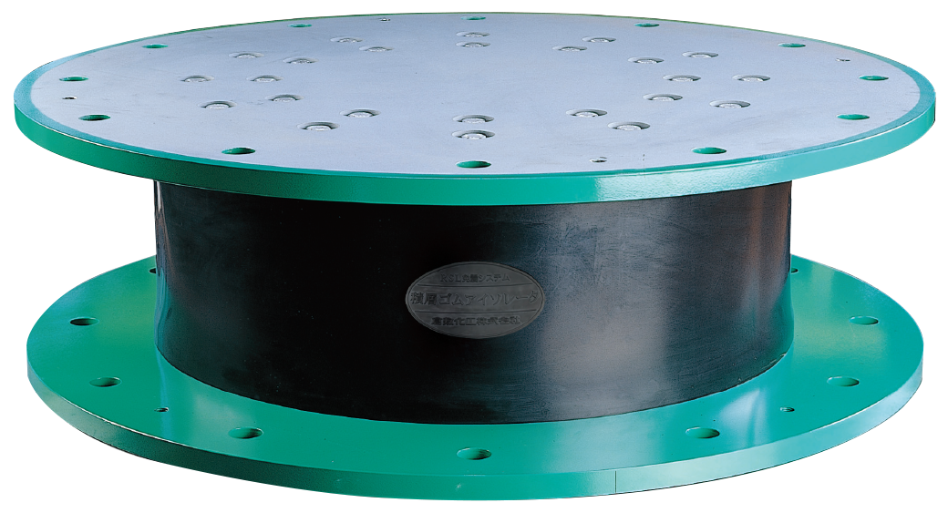
Seismic isolation laminated rubber

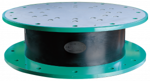

Kurashiki laminated rubber isolator is an intermediate steel plate exposed type in which the intermediate steel plate is exposed on the side.
Furthermore, there is no central hole, and it exhibits stable performance even under high surface pressure.
The structure of the Kurashiki laminated rubber isolator is a reinforced structure without a central hole.
We have realized the production of a laminated rubber isolator that does not require a center hole with our original development technology.
Laminated rubber isolators with no central hole have a strong shaft and exhibit excellent performance even under high surface pressure.
Therefore, it is possible to maintain a stable restoring force, and the structure is resistant to buckling even when the laminated rubber is greatly deformed.
For the natural rubber used in Kurashiki laminated rubber, only raw materials with stable quality are imported and used under a strict inspection system.
When the surface pressure acting on the laminated rubber is relatively low, that is, when the building is relatively lightweight, the spring constant must be lowered in order to lengthen the period of the building.
The NB30 and NB35 series have a low spring constant and can lengthen the natural period even when the surface pressure is relatively low.
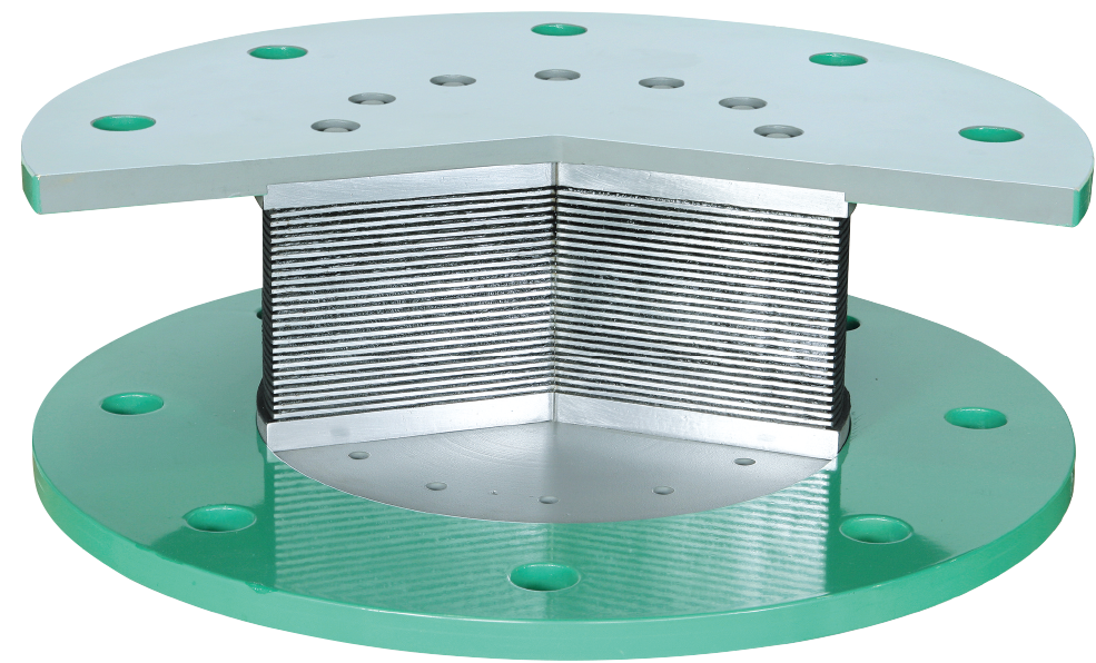
Laminated rubber isolators are important products that support building loads and play a role in mitigating the transmission of seismic forces to buildings by softly deforming in the horizontal direction during an earthquake.
Alternate layers of rubber and steel plates are placed in a mold and molded. Various inspections are performed at important points in the manufacturing process to ensure product quality.
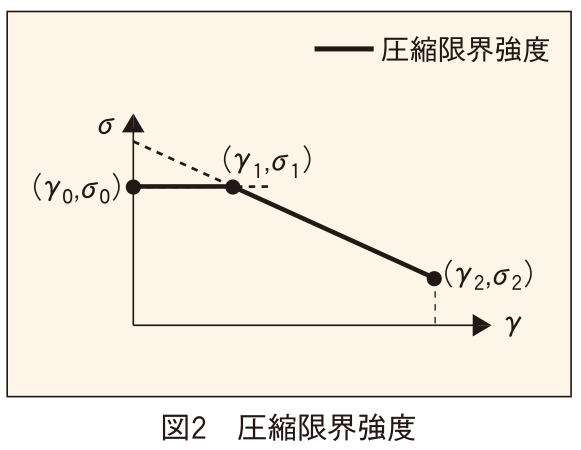
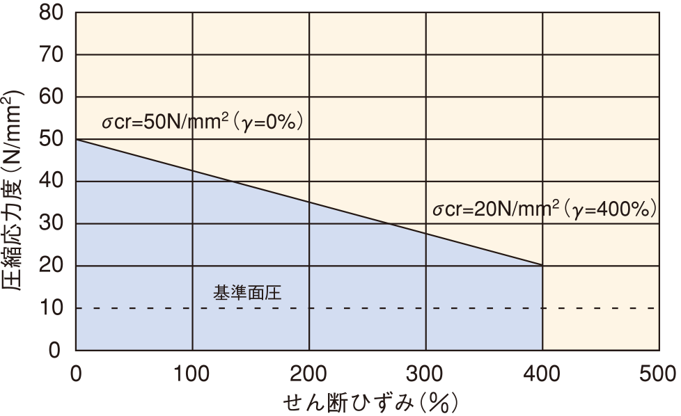
Limit performance: Limit strain 400% (contact pressure 10 and 0N/mm2)
Vertical performance: compressive limit strength 50N/mm2 (shear strain 0%), 20N/mm (shear strain 400%)
: Tensile limit strength 1.0N/mm2
| Item | NB30- | 500 | 550 | 600 | 650 | 700 | 750 | 800 | 850 | 900 | 1000 | 1100 | ||
|---|---|---|---|---|---|---|---|---|---|---|---|---|---|---|
| Material composition | Shear modulus | G. | (N/mm²) | 0.29 | ||||||||||
| Of each part shape, dimensions | Internal rubber outer diameter | Do | (mm) | 500 | 550 | 600 | 650 | 700 | 750 | 800 | 850 | 900 | 1000 | 1100 |
| Internal rubber inner diameter | Di | (mm) | 0 | |||||||||||
| Internal rubber layer thickness | Tr | (mm) | 3.75 | 4.15 | 4.5 | 4.9 | 5.3 | 5.7 | 6 | 6.4 | 6.8 | 7.5 | 8.3 | |
| Number of internal rubber layers | n | 26 | ||||||||||||
| Internal rubber total thickness | Hours | (mm) | 97.5 | 107.9 | 117 | 127.4 | 137.8 | 148.2 | 156 | 166.4 | 176.8 | 195 | 215.8 | |
| Primary shape factor | S1 | 33 | ||||||||||||
| Quadratic shape factor | S2 | 5.1 | ||||||||||||
| Intermediate steel plate thickness | Ts | (mm) | 3.2 | 3.2 | 3.2 | 3.2 | 4.5 | 4.5 | 4.5 | 4.5 | 4.5 | 4.5 | 4.5 | |
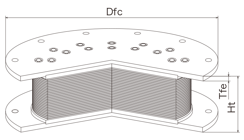
| Flange thickness (end) | Tfe* Note 1) | (mm) | 25 | 25 | 25 | 25 | 25 | 25 | 30 | 30 | 36 | 36 | 36 | |
| Flange thickness (center) | Tfc *Note 1) | (mm) | 21 | 21 | 21 | 21 | 20.5 | 20.5 | 24.8 | 24.8 | 27.8 | 27.8 | 29.5 | |
| Outer diameter of flange | Dfc *Note 1) | (mm) | 780 | 830 | 880 | 930 | 1000 | 1075 | 1150 | 1200 | 1250 | 1400 | 1550 | |
| Product height | Ht *Note 1) | (mm) | 251.5 | 261.9 | 283 | 293.4 | 334.3 | 344.7 | 362.5 | 372.5 | 399.3 | 419.5 | 442.5 | |
| Product mass | *Note 1) | (kg) | 380 | 450 | 560 | 640 | 850 | 990 | 1210 | 1350 | 1640 | 2060 | 2460 | |
| Marginal performance | Critical strain | γcr (%) | When contact pressure = 0 | 400 | ||||||||||
| At standard surface pressure | 400 | |||||||||||||
| Horizontal deformation at critical strain | (mm) | 390 | 432 | 468 | 510 | 551 | 593 | 624 | 666 | 707 | 780 | 863 | ||
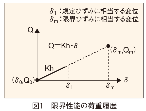
| Load history *Note 2) | (kN) | Q=Kh×γ×Hr | ||||||||||||
| Vertical performance | Compressive strength limit (N/mm²) *Note 3) | (γ₀,σ₀) | (0 , 50) | |||||||||||
| (γ₁,σ₁) | - | |||||||||||||
| (γ₂,σ₂) | (400, 20) | |||||||||||||
| Vertical stiffness | Kv | (×10³kN/m) | 2020 | 2200 | 2430 | 2610 | 2780 | 2950 | 3240 | 3410 | 3590 | 4050 | 4390 | |
| Reference surface pressure | Kv | (N/mm²) | 10 | |||||||||||
| Ultimate tensile strength | (N/mm²) | γ=100% | 1 | |||||||||||
| Pressure receiving area | (×10³mm²) | 196 | 238 | 283 | 332 | 385 | 442 | 503 | 567 | 636 | 785 | 950 | ||
| Support load at standard surface pressure | (kN) | 1960 | 2380 | 2830 | 3320 | 3850 | 4420 | 5030 | 5670 | 6360 | 7850 | 9500 | ||
| Horizontal performance | Horizontal stiffness | Kh | (×10³kN/m) | 0.59 | 0.65 | 0.71 | 0.76 | 0.82 | 0.87 | 0.95 | 1 | 1.06 | 1.19 | 1.29 |
| Specified strain | γ₀ | (%) | 100 | |||||||||||
| Manufacturing variation | Variation in Kh | (%) | Within ±20 | |||||||||||
| Kv variation | (%) | Within ±30 | ||||||||||||
| Of horizontal performance Rate of change | Temperature dependence | Rate of change of Kh (%) | (-10℃) / (20℃) | +9 or less | ||||||||||
| (0℃) / (20℃) | +6 or less | |||||||||||||
| (30℃) / (20℃) | -3 or more | |||||||||||||
| (40℃) / (20℃) | -3 or more | |||||||||||||
| Aging rate | Rate of change in Kh (%) | (equivalent to 60 years) | +10 or less | |||||||||||
| Strain dependence | Kh ratio | (γ=0.5) / (γ=1.0) | 1.09 ± 0.05 | |||||||||||
| (γ=2.0) / (γ=1.0) | 0.89 ± 0.05 | |||||||||||||
| Percentage change in creep strain ε cp (%) | Equivalent to 20℃ x 60 years | 6 or less | ||||||||||||
*Note 1) These are the values for our standard products. The flange dimensions can be changed to other dimensions within the range that meets the ministerial approval. Please contact us for details.
*Note 2) See Figure 1
*Note 3) See Figure 2

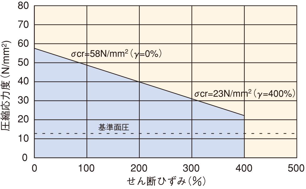
Limit performance: Limit strain 400% (contact pressure 10 and 0N/mm2)
Vertical performance: compressive limit strength 50N/mm2 (shear strain 0%), 20N/mm (shear strain 400%)
: Tensile limit strength 1.0N/mm2
| Item | NB30- | 500 | 550 | 600 | 650 | 700 | 750 | 800 | 850 | 900 | 1000 | 1100 | ||
|---|---|---|---|---|---|---|---|---|---|---|---|---|---|---|
| Material composition | Shear modulus | G. | (N/mm²) | 0.34 | ||||||||||
| Of each part shape, dimensions | Internal rubber outer diameter | Do | (mm) | 500 | 550 | 600 | 650 | 700 | 750 | 800 | 850 | 900 | 1000 | 1100 |
| Internal rubber inner diameter | Di | (mm) | 0 | |||||||||||
| Internal rubber layer thickness | Tr | (mm) | 3.75 | 4.15 | 4.5 | 4.9 | 5.3 | 5.7 | 6 | 6.4 | 6.8 | 7.5 | 8.3 | |
| Number of internal rubber layers | n | 26 | ||||||||||||
| Internal rubber total thickness | Hours | (mm) | 97.5 | 107.9 | 117 | 127.4 | 137.8 | 148.2 | 156 | 166.4 | 176.8 | 195 | 215.8 | |
| Primary shape factor | S1 | 33 | ||||||||||||
| Quadratic shape factor | S2 | 5.1 | ||||||||||||
| Intermediate steel plate thickness | Ts | (mm) | 3.2 | 3.2 | 3.2 | 3.2 | 4.5 | 4.5 | 4.5 | 4.5 | 4.5 | 4.5 | 4.5 | |
| Flange thickness (end) | Tfe* Note 1) | (mm) | 25 | 25 | 25 | 25 | 25 | 25 | 30 | 30 | 36 | 36 | 36 | |
| Flange thickness (center) | Tfc *Note 1) | (mm) | 21 | 21 | 21 | 21 | 20.5 | 20.5 | 24.8 | 24.8 | 27.8 | 27.8 | 29.5 | |
| Outer diameter of flange | Dfc *Note 1) | (mm) | 780 | 830 | 880 | 930 | 1000 | 1075 | 1150 | 1200 | 1250 | 1400 | 1550 | |
| Product height | Ht *Note 1) | (mm) | 251.5 | 261.9 | 283 | 293.4 | 334.3 | 344.7 | 362.5 | 372.5 | 399.3 | 419.5 | 442.5 | |
| Product mass | *Note 1) | (kg) | 380 | 450 | 560 | 640 | 850 | 990 | 1210 | 1350 | 1640 | 2060 | 2460 | |
| Marginal performance | Critical strain | γcr (%) | When contact pressure = 0 | 400 | ||||||||||
| At standard surface pressure | 400 | |||||||||||||
| Horizontal deformation at critical strain | (mm) | 390 | 432 | 468 | 510 | 551 | 593 | 624 | 666 | 707 | 780 | 863 | ||
| Load history *Note 2) | (kN) | Q=Kh×γ×Hr | ||||||||||||
| Vertical performance | Compressive strength limit (N/mm²) *Note 3) | (γ₀,σ₀) | (0 , 58) | |||||||||||
| (γ₁,σ₁) | - | |||||||||||||
| (γ₂,σ₂) | (400 , 23) | |||||||||||||
| Vertical stiffness | Kv | (×10³kN/m) | 2250 | 2450 | 2660 | 2860 | 3070 | 3270 | 3470 | 3680 | 3880 | 4300 | 4790 | |
| Reference surface pressure | Kv | (N/mm²) | 12.5 | |||||||||||
| Ultimate tensile strength | (N/mm²) | γ=100% | 1 | |||||||||||
| Pressure receiving area | (×10³mm²) | 196 | 238 | 283 | 332 | 385 | 442 | 503 | 567 | 636 | 785 | 950 | ||
| Support load at standard surface pressure | (kN) | 2450 | 2970 | 3530 | 4150 | 4810 | 5520 | 6280 | 7090 | 7950 | 9820 | 11880 | ||
| Horizontal performance | Horizontal stiffness | Kh | (×10³kN/m) | 0.69 | 0.76 | 0.83 | 0.89 | 0.96 | 1.02 | 1.11 | 1.17 | 1.24 | 1.38 | 1.51 |
| Specified strain | γ₀ | (%) | 100 | |||||||||||
| Manufacturing variation | Variation in Kh | (%) | Within ±20 | |||||||||||
| Kv variation | (%) | Within ±30 | ||||||||||||
| Of horizontal performance Rate of change | Temperature dependence | Rate of change of Kh (%) | (-10℃) / (20℃) | +9 or less | ||||||||||
| (0℃) / (20℃) | +6 or less | |||||||||||||
| (30℃) / (20℃) | -3 or more | |||||||||||||
| (40℃) / (20℃) | -3 or more | |||||||||||||
| Aging rate | Rate of change in Kh (%) | (equivalent to 60 years) | +10 or less | |||||||||||
| Strain dependence | Kh ratio | (γ=0.5) / (γ=1.0) | 1.07 ± 0.05 | |||||||||||
| (γ=2.0) / (γ=1.0) | 0.91 ± 0.05 | |||||||||||||
| Percentage change in creep strain ε cp (%) | Equivalent to 20℃ x 60 years | 6 or less | ||||||||||||
*Note 1) These are the values for our standard products. The flange dimensions can be changed to other dimensions within the range that meets the ministerial approval. Please contact us for details.
*Note 2) See Figure 1
*Note 3) See Figure 2
Feel free to contact us for a quote or inquiry


All rights reserved, © Copyright Kurashiki Kako Co., Ltd.
Feel free to contact us for a quote or inquiry